An intercom is close to home media communications gadget which encourages the trading of messages between at least two areas where standard vocal correspondence would be troublesome or outlandish because of separation or impediments. Essential intercom frameworks have been in presence since about 10 years into the twentieth century if you just consider plans dependent on that fairly helpful development of Alexander Bell’s; the phone.
How to Make a Simple Intercom Circuit?
An intercom is an electrical device allowing sending and receiving messages between two points. This engineering project is for the construction and testing of a chosen Electronic circuit or system. Circuit of an intercom is so simple and consists of few components. The circuit just uses a solitary IC for the intensification reason and a couple of speakers alongside a bunch of inactive segments for gaining the expecting intercom application circuit. The circuit can be implemented on a proto-board or a strip-board or a Printed Circuit Board (PCB).
Step 1: Collecting the Components
The best approach to start any project is to make a complete list of components. This is not only an intelligent way to start a project but it also saves us from many inconveniences in the middle of the project. A list of components of this project is given below: You can view the circuit diagram to confirm the quantity of the components used in a single circuit.
Step 2: Studying the Components
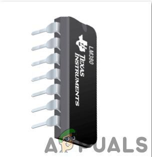
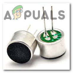
Now as we have a complete list of all the components that we are going to use in our project. Let us move one step ahead and go through a brief study of some components. LM380 is an amplifier IC, specially designed to amplify the user’s audio signal. Its gain is normally fixed up to 34dB. In this amplifier IC, the output automatically maintains its level to half of the supplied input voltage. Several features of this amplifier include three ground pins, wide supply voltage range, low distortion, high peak voltage, etc. Other than Intercom circuits, it can be used in alarms, televisions, sound systems, and photograph amplifiers, etc. A speaker is a transducer whose job is to produce audio signals that can be heard by a user. It performs this task by converting the electromagnetic waves that are generated by the computer or any other audio transmitters, to an audio signal. The input to the speaker may be in the form of analog or digital. There are many specifications of different speakers for example power handling, size, frequency response, etc. The speaker we are using has an internal impedance of 8-ohm and a power handling of 1 Watt. An Electret Microphone is a capacitor-based microphone. By using this microphone, the need for polarizing power supply is eliminated by using a permanently charged material, used to convert sound into an electrical signal. An electret is a ferroelectric material that has been for all time electrically charged or energized. Because of the high obstruction and substance steadiness of the material, the electrical charge won’t rot for many years. The name originates from “electrostatic and magnet”; a static charge is inserted in an electret by the arrangement of the static charges in the material, much how a magnet is made by adjusting the attractive spaces in a bit of iron. These Mics are widely used in GPS systems, hearing aids, telephones, voice over IP, Speech recognition, FRS Radios, etc.
Step 3: Scope of Study
The point and goal of this task are to structure and develop a basic intercom framework (for the most part two correspondence stations) as a way to supplant man’s work and worry of strolling over given premises for data conveyance. These station wired intercom framework can be utilized as an entryway telephone, associating from the house to the way to screen guests to your home. The wife, in the wake of getting ready supper, can through this framework approach the husband in his room to the supper table. By and large, an intercom framework can be utilized for message communicate (if there should be an occurrence of multi-channel intercom), as entryway telephone, observing and so on. The extent of this venture work is restricted to the plan, development, and test on a two-station basic intercom framework with particular that;
The demodulator ought to work with base mutilation while creating a sufficient yieldThe small-signal amplifier must provide an undistorted signal into the buffer amplifier to be able to drive a speaker of Impedance.A 9-volt d.c control supply is to be a plan and utilized to control the basic intercom for a task, at each station.The mater and the remote stations will be built individually.Result’ will completely be examined while proposals for further examination made.
Step 4: Construction
The construction of an intercom is very simple. This intercom circuit dependent on the IC LM380 sound enhancer requires not many outer parts. In this way, the circuit is extremely simple to collect and the segments are promptly accessible in the market on the off chance that we need to structure a model. The circuit outline of the intercom appears in Fig. 1. Notwithstanding sound intensifier LM380 (IC1), it utilizes a condenser amplifier (MIC1), an 8-ohm, 0.5W speaker and a couple of different segments.3.1.2 Methods The intercom circuit shown below can be constructed on three different boards that are, proto-board, strip-bard, and Printed Circuit Board (PCB). Amass a similar circuit on two separate units. To utilize these units as an intercom, extend the output (LS1) of the principal unit to the second unit set in a remote area and the other way around. Set the required sound dimension by altering potentiometer VR1. Close the switch S2 quickly to produce a sound tone in the speaker (LS1). This circuit works off a 9V DC battery.
Step 5: Making the Hardware
First of all, the intercom circuit was constructed on a breadboard for testing purposes. When the results were confirmed to be correct on a breadboard, the circuit was re-generated on proto-board or a stripboard or the PCB. On the proto-board, the components are placed. Then the wiring was planned by using a proto-board planning sheet. To connect the components using Kynar wire, strip the end of the wire about 2mm, measure the length of the required wire and strip the other end. Loop the bare wire ends and place the loops around the pins of components, crimp them so they provide a temporary hold and finally solder the connections to make the connections permanent. If you want to make the circuit on a stripboard then, the type of stripboard was selected, in the first place. Vero-board is better to be chosen for this task because the only headache is to place components on Vero-board and just solder them and check the continuity using the Digital Multi Meter. Once the circuit layout is known, cut the board into a reasonable size. For this purpose place the board on the cutting mat and by utilizing a sharp blade (securely) and by taking all the safety precautions, more than once score the load up top and base along the straight edge (5 or multiple times), running over the apertures. After doing so, place the components on the board closely to form a compact circuit and solder the pins according to the circuit connections. In case of any mistake, try to de-solder the connections and solder them again. Finally, check the continuity. A PCB is a printed circuit board. It is a board fully coated with copper on one side and fully insulating from the other side. Making the circuit on the PCB is comparatively a lengthy process. Firstly, the circuit is designed on software and simulated. After that, a PCB layout is made using that software e.g. Proteus Professional, OR CAD software, the circuit layout is printed on a butter paper. Then the butter paper is placed on the PCB board and ironed until the circuit is printed on the board (It takes approximately five minutes). Now, when the circuit is printed on the board, it is dipped into the FeCl3 solution to remove extra copper from the board, only the copper under the printed circuit will be left behind. After that rub the PCB board with the scrapper so the wiring will be prominent. Now drill the holes in the respective places and place the components on the circuit board. Solder the components on the board. Finally, check the continuity of the circuit and if discontinuity occurs at any place de-solder the components and connect them again. Make sure you follow the following circuit diagram.
Step 6: Testing
After the circuit is made, first of all, check all the connections, especially the soldered ends of the component’s pins. After that pass the circuit through a continuity test. A continuity test tells if two points have a connection between them or not. This is done using a Digital Multi Meter If no error occurs up till now, connect the circuit to the power supply and measure the readings using a Digital Multi-Meter. The graph of input and output signal can be tested to check if the amplification is being done or not. An oscilloscope is used to generate a sinusoidal signal for testing purposes.
Applications
There is a wide range of applications where an intercom circuit can be used. Some of these applications are listed below.
How To Measure Distance Between Two Points Using Arduino?How to Increase Signal Strength for Weak Wifi Signal on LinuxHow to use Google Home as an Intercom?How To Make a Pickpocket Alarm Circuit?